






















How Wireless Remote Controls Integrate with PLC Systems
Blog , Technical Resources • Posted on September 24, 2026 at 11:04 am
A technical guide for OEM engineers and integrators on wireless control architecture, communication protocols, and safety design for PLC-based machinery
Modern industrial machines rarely operate as standalone systems. Whether it’s a mobile crane, a dredge, a conveyor line, or industrial cleaning equipment, most OEMs rely on a programmable logic controller (PLC) as the central control platform. Adding a wireless remote control to that machine is not simply a matter of swapping a cable pendant for a transmitter.
A wireless remote control doesn’t operate motors, pumps, or valves directly — it communicates with the PLC, and the PLC decides how the machine responds. The transmitter sends the operator’s command to a receiver mounted on the machine; the receiver converts that signal into something the PLC can read; the PLC executes the logic. Getting this hand-off right (architecture, protocol, and safety) is what determines whether a wireless upgrade is plug-and-play or a redesign.
For OEM engineers, integrators, and technical buyers, this guide breaks down how that hand-off works, the two ways it’s typically built, and the design factors that separate a reliable integration from a support ticket.
1. Wireless Remote Control PLC integration: Where Wireless Remotes Fit in a PLC-Controlled Machine
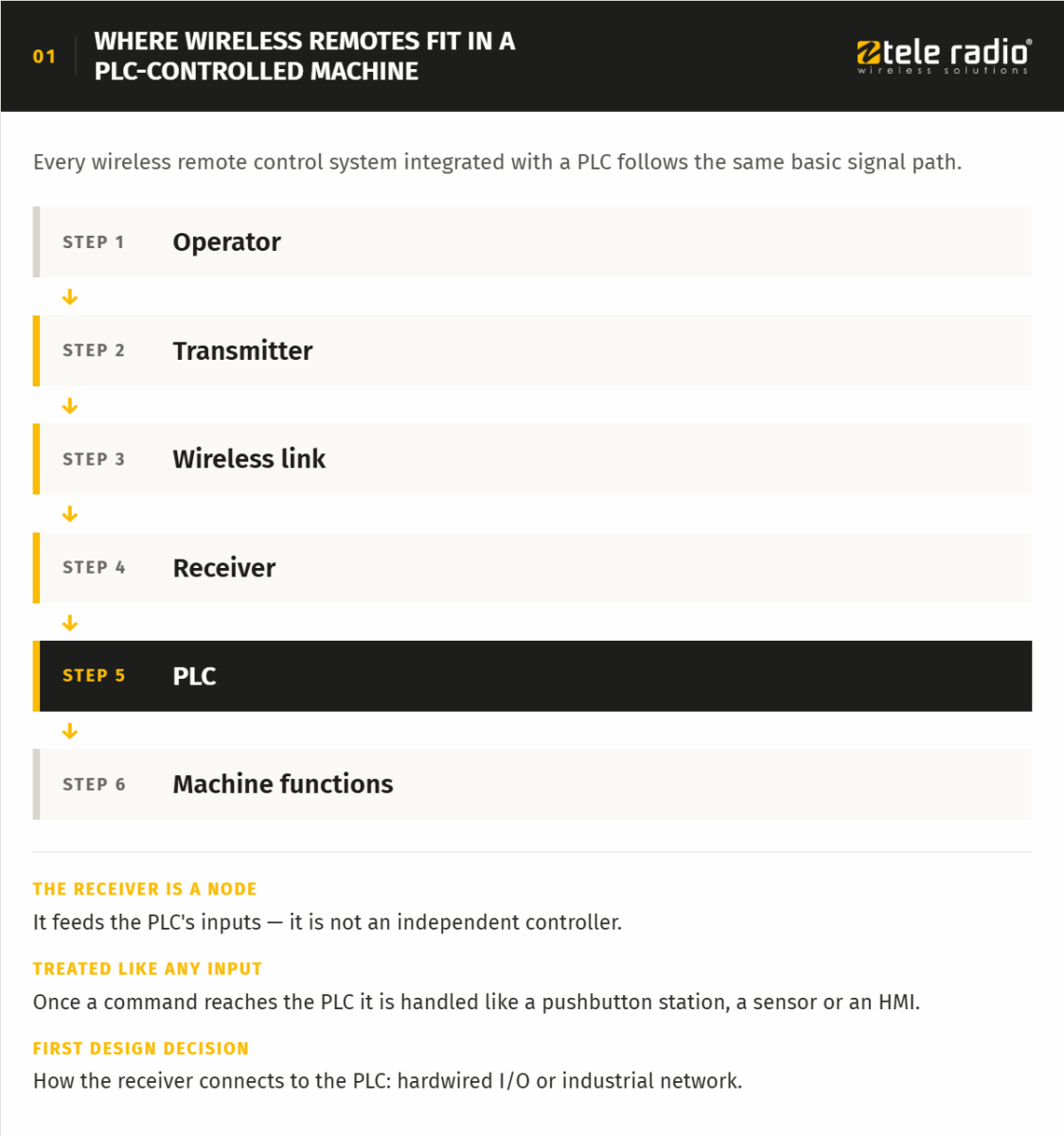
Every wireless remote control system integrated with a PLC follows the same basic signal path.
The receiver is a node feeding the PLC’s inputs — not an independent controller. Once a command reaches the PLC, it’s treated the same way as a signal from a pushbutton station, a sensor, or an HMI. This is what allows a wireless system to be absorbed into a machine’s existing control logic rather than bolted on as a separate system, and it’s why the receiver’s connection method to the PLC is the first real design decision.
2. Two Integration Approaches: Hardwired I/O vs. Network/Fieldbus
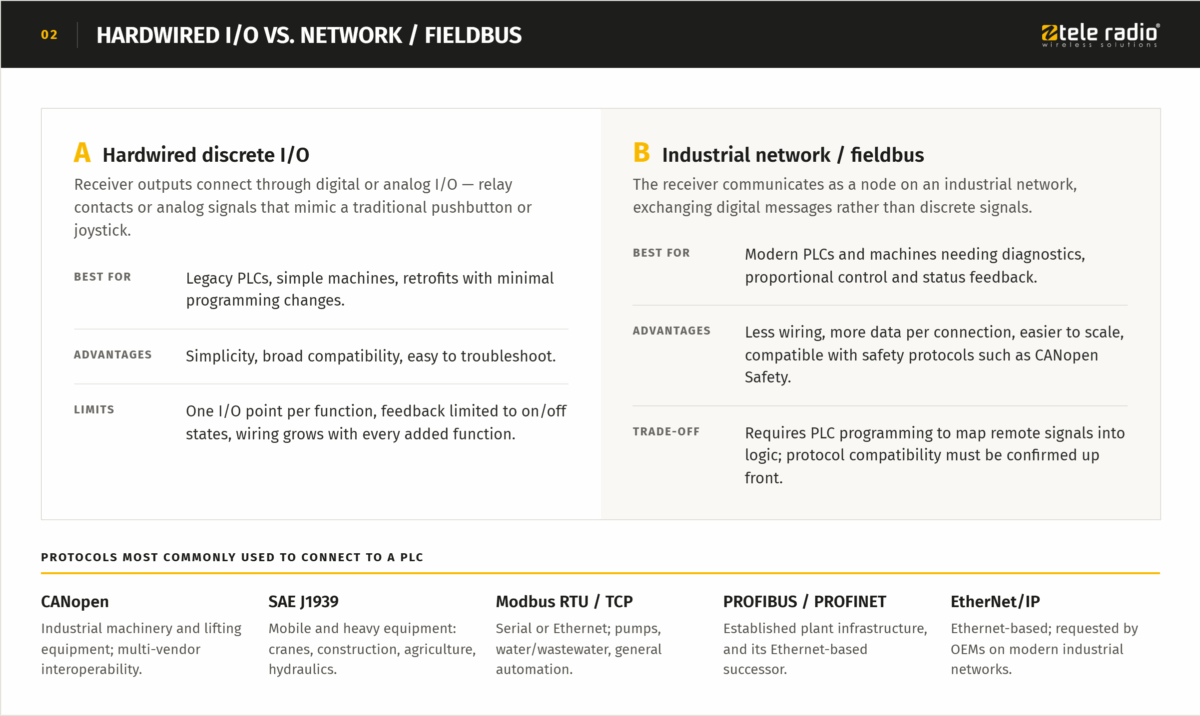
There are two established ways to do the wireless remote control PLC integration:
A. Hardwired discrete I/O
The receiver’s outputs connect to the PLC through digital or analog I/O — relay contacts or analog signals that mimic a traditional pushbutton or joystick.
- Limitations: each function needs a dedicated I/O point, feedback is limited to on/off states, and wiring complexity grows with every added function.
- Best for: legacy PLCs, simple machines, retrofits with minimal programming changes.
- Advantages: simplicity, broad compatibility, easy to troubleshoot.
B. Industrial network / fieldbus
The receiver communicates with the PLC as a node on an industrial communication network, exchanging digital messages rather than discrete signals.
Trade-off: requires PLC programming to map remote signals into logic, and protocol compatibility has to be confirmed up front.
Best for: modern PLCs and machines that need richer data exchange — diagnostics, proportional control, status feedback.
Advantages: less wiring, more data per connection, easier to scale, and compatible with standardized safety protocols such as CANopen Safety.
The protocols most commonly used to connect wireless remote controls to PLCs include:
- CANopen — industrial machinery and lifting equipment, widely used for multi-vendor interoperability.
- SAE J1939 — mobile and heavy equipment: cranes, construction, agricultural, and hydraulic machinery.
- Modbus RTU / Modbus TCP — serial or Ethernet-based, common in pump systems, water/wastewater, and general industrial automation.
- PROFIBUS / PROFINET — PROFIBUS remains common in established plant infrastructure; PROFINET is its Ethernet-based successor in newer automation environments.
- EtherNet/IP — Ethernet-based, increasingly requested by OEMs standardizing on modern industrial networks.
Not sure whether your application needs discrete I/O or a fieldbus connection? It depends on the number of functions, the feedback you need, and the PLC already on the machine.
Map your architecture before you commit to hardware.
3. Key Design Considerations for PLC-Wireless Integration
Beyond choosing I/O or fieldbus, five factors determine whether an integration holds up in the field:
- Compatibility & architecture fit: The wireless system needs to match the machine’s existing PLC hardware, available I/O, and supported network — not the other way around. Forcing a mismatch (e.g., a relay-only receiver onto a machine that expects network diagnostics) creates unnecessary wiring and blind spots.
- Safety integration: Emergency stop and other safety functions must meet the risk level of the application, most commonly assessed against EN ISO 13849-1 (Performance Level, PL a-e) or EN/IEC 62061 (Safety Integrity Level, SIL 1-3). Reliable systems use a dual-channel design — a physical relay path plus independent monitoring over the radio link — so a fault on either channel triggers a stop. Hardwired safety circuits and networked safety protocols (like CANopen Safety) both need to be verified against the required PL/SIL for the specific hazard, not assumed from a datasheet.
- Latency & real-time performance: Wireless response time has to stay compatible with the PLC’s scan cycle, especially for proportional or continuous control functions where delay directly affects machine behavior.
- Scalability & modularity: Machines evolve. An architecture that started as simple I/O may later need to support additional functions or machine variants — network-based integration generally scales with fewer hardware changes.
- Diagnostics & monitoring: Fieldbus integration allows the receiver to report battery level, signal strength, and fault codes directly into the PLC or HMI, turning the remote into a source of maintenance data rather than just a control input.
4. Real-Time Feedback: Two-Way Communication
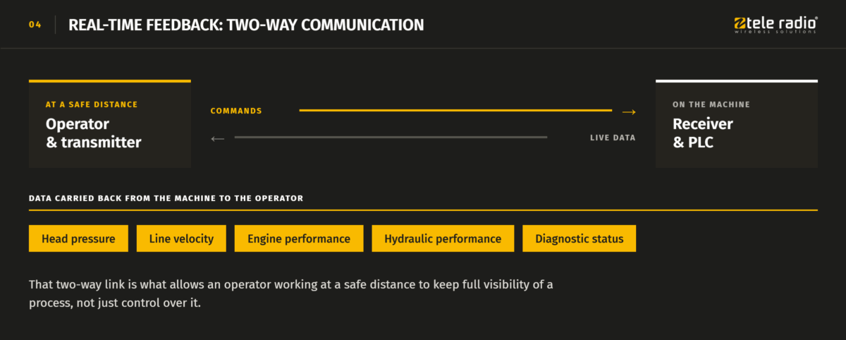
Wireless systems integrated with a PLC are no longer limited to sending commands one way. In many applications, they also carry live data back from the machine to the operator — head pressure, line velocity, engine performance, hydraulic performance, and diagnostic status. That two-way link is what allows an operator working at a safe distance to keep full visibility of a process, not just control over it.
5. Choosing the Right Communication Method
Favor hardwired I/O when: the machine has a small, fixed number of functions, uses a legacy PLC, or the priority is minimal engineering effort on a straightforward retrofit.
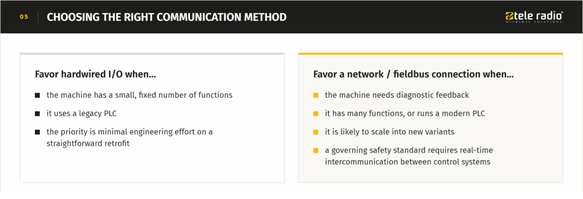
Favor a network/fieldbus connection when: the machine needs diagnostic feedback, has many functions, runs a modern PLC, is likely to scale into new variants, or a governing safety standard requires real-time intercommunication between control systems (see the tandem crane example below).
Example Architecture 1: Hazardous-Material Transfer Operation
Challenge: Moving hazardous chemical and petroleum slurries over long distances and steep grades, using a dredge and multiple booster pumps operating together — in a process that has to run continuously, safely, and under full operator visibility.
Requirements: control of multiple machines from one position, continuous operation up to 24 hours a day, a safe operator standoff distance, and real-time visibility into process conditions.
Architecture:
Operator → TEQ Line transmitter → Wireless link → Receiver → PLC
- Dredge
- Booster pump(s)
- Process sensors
- Safety logic
A machine design engineering company in Mississippi, USA, worked with Tele Radio’s application engineers to build this architecture around a TEQ Line belly box system. The on-board PLC acts as the command center, coordinating the dredge and booster pumps, reading sensor feedback, and enforcing the machine’s safety logic — all from a single master transmitter, so one operator can run multiple machines individually or simultaneously.
The real-time link between transmitter and PLC does more than send commands: head pressure, line velocity, and engine/hydraulic performance are fed back to the operator continuously. That closed loop is what lets the system self-coordinate — for example, when the main pump approaches its maximum working head pressure, the booster pump rpm increases in sync to maintain the slurry transfer; if an over-pressure state is triggered, the operation slows immediately. The result is coordinated, predictable behavior across multiple machines instead of independent units reacting on their own.
The system integrated into the original machine design with minimal modification, which matters as much as the architecture itself: an integration that requires redesigning the machine defeats the purpose of adding wireless control in the first place. As with the protocols above, this class of system is typically compatible with CANopen, J1939, Modbus, PROFIBUS, PROFINET, or EtherNet/IP, so the same architecture pattern adapts to different plant or machine standards.
Example Architecture 2: Tandem Crane Synchronization
Challenge: Lifting large or extremely heavy loads with two overhead cranes working together (“tandem mode”) demands perfectly synchronized movement — any mismatch between the two cranes risks overload or an accident.
Requirements: one operator controlling two cranes, individually or simultaneously; continuous real-time synchronization between both cranes’ control systems; compliance with crane-specific lifting standards.
Architecture:
Operator → Tiger master transmitter → Wireless link → Receiver – Crane 1 → CTC link → Receiver – Crane 2
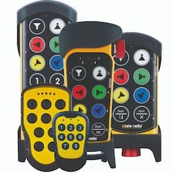
Strong Machines, a Brazilian overhead crane manufacturer, built this architecture around Tele Radio’s Tiger system with Crane-to-Crane (CTC) transceivers installed on each crane. A single master transmitter lets one operator run both cranes, and at any time the operator can select which bridge or trolley to control — from a position with a clear line of sight and a safe distance from the load.
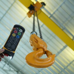
The CTC link keeps both cranes’ control systems talking in real time: when one hoist reaches its first limit switch, both cranes reduce speed in sync; if the second limit is triggered, the operation stops immediately. This isn’t just a nice-to-have — uneven load distribution between two independently controlled cranes is a real physical risk, and synchronized intercommunication is what keeps that risk in check, regardless of jurisdiction. Unlike the hazardous-material example above, the constraint here comes from the physics of coordinated load-sharing rather than process feedback — exactly the kind of requirement worth engineering for before an incident makes the case for you.
Ready to plan your integration?
Get the decision framework,
reference diagrams, and additional
integration examples across machine types




 Tele Radio supports the world wide preservation of the Tiger with WWF.